Testing with Power Hardware in the Loop Capabilities

AC Power Hardware in the Loop (PHIL) Grid Connected Test Applications
What is Power-Hardware-in the-Loop?
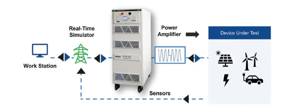
Power-Hardware-in-the-Loop (PHIL) allows users to perform realistic closed loop tests without the need for testing on a real system.
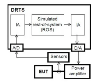
PHIL provides a real-time simulation environment through the exchange of low voltage/current signals that can be employed for the higher power testing required by the Unit Under Test (UUT). To this end, a power amplifier is used in between the UUT and the low-level simulator I/O to provide close-loop feedback between the simulation and the physical UUT. A power amplifier is selected based on their close-loop performance and ability to generate or to sink power.
Why is PHIL Important
PHIL shortens the design cycle by simulating control algorithms on the Real Time System (RTS), which uses a transient approach that provides instantaneous voltages and currents.
This workflow allows for accurate emulation of a physical power plant and a multitude of loads. The high-fidelity simulation provides the flexibility to apply tests that are not practical on a real testbed which is ideal for testing R&D, inter-operability of loads and prototyping applications, safely.
PHIL is a powerful testing capability for the testing and validation of power components and systems with higher power flow between the UUTs. Ideal applications include testing grid-tied inverters for compliance to IEEE 1547.1, UL1741 and similar global standards.
Key Applications
- Aerospace and Defense
- Electric Vehicles
- Electric Motor Drives
- Renewable Energy
- Microgrids, PV inverters, Utility Grid, Wind Turbines
- Marine and Offshore Power Systems
- Industrial Automation and Manufacturing, Robotics
- Universities, Research Labs
Selecting the Right Test Solution for PHIL Test Applications
Key considerations for selecting a PHIL test solution include wide power range, 4-quadrant capability, PHIL bandwidth, safety, and additional testing requirements.
Finding the right solution for PHIL testing can reduce test time, eliminate errors, and optimize performance. It is critical to evaluate the overall test objectives when selecting a test solution. You may want to consider whether there are additional test objectives that can be met so that you can test your grid-tied products, effectively.
1. Wide Operating Envelope
When designing a PHIL testbed, it is important to consider the varying operating ranges of the UUTs that will be tested.
Selecting a wide operating envelope will allow you to test a broad selection of grid-tied products as well as provide additional test coverage to address overcurrent, overvoltage, or temporary overloads.
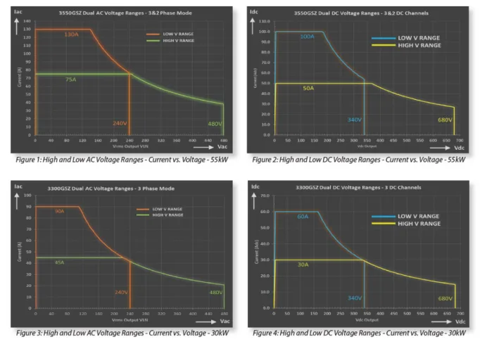
The AZX Series provides a wide range of power, frequency, and phase configuration settings that provide the ultimate flexibility as shown in Figure 2.
The dual range output provides users with the option to switch between two different voltage and current range combinations according to their UUT current/power requirements which supports a wider range of devices that can be simulated.
2. Extra Current Availability
The AZX Series’ low voltage range supports simulation of grid voltages to 240Vac while offering twice the available current compared to its high voltage range setting. For higher voltage grid simulations such as 277/480 or 346/600 voltage simulations, the high voltage range is available.
3. Six Real-Time Feedback Signals
The AZX Series has a highly responsive measurement signal on voltage and current. This allows for the signals to feed into the RTS for close loop control with greater precision.
The unit provides six real-time feedback signals with fast response to the PHIL system, 3 for Voltage and 3 for current.
4. PHIL Bandwidth with Low Latency < 50
It is very important to determine the main objectives of the tests to be performed with the PHIL system. The test objectives will determine the real-time simulator time step and amplifier bandwidth requirements.
Low latency, fast response time, and high bandwidth is critical for fast and responsive feedback to emulate real-time simulation of PHIL systems.
Example 1: Amplifier Response Times Evaluation
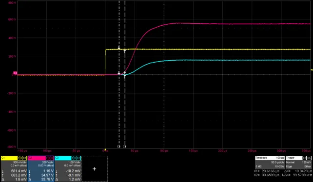
The AZX Series amplifiers have a low latency of less than 50μs and fast input to output step response. These short delays allow for realistic closed-loop tests.
As shown in the chart on the right, the shortest rise time recorded is in the 45 usec range and the output to feedback signal response which is about 10 usec.
- Step response at 550 V
- 18 ohms (approx.) load
- 30 A load current
- 16.5 kW load
- Delay from reference input to output = 21 μs
- Output rise time (10% to 90%) = 45 μs
- Output to feedback delay = 10 μs
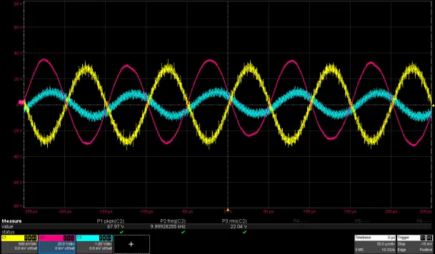
Example 2: High Frequency Application / AC
In this high frequency example, the simulation runs at 10kHz with a lower RMS voltage required by amplifier output filter restrictions.
The tests was done at higher AC frequencies to determine suitability for non-grid simulation applications.
- Steady state response at 40 Vrms L-N reference
- 6 ohms (approx.) load
- Output voltage = 22 Vrms
- Output frequency = 10 kHz
- Phase delay between reference input & output = 50 μs
- Output to feedback delay = 10 us
5. Harmonic Signal Simulation
Simulating harmonic and interhamonics on top of the mains frequency is also important for PHIL simulation. The higher bandwidth the amplifier used supports, the wider frequency harmonic range can be simulated. The AZX series can support harmonics up to 10kHz, which far exceeds the requirements for testing grid-tied systems, as shown in Figure 6.
6. 4-Quadrant Capability: Sourcing & Sinking
The UUT generates power which the amplifier needs to be able to absorb and in other cases, the UUT may require a power input, in which the power amplifier needs to source power. To simulate a power grid, the power amplifier has to have 4-quadrant capability to support both sourcing and sinking power.
7. Safety: Galvanic Isolation
For amplifiers that use analog inputs and outputs, there are specific considerations to ensure safety. At the top of this list is Galvanic isolation. Galvanic isolation is a complete physical separation between the input and output which prevents ground loops and thereby, reduces safety risks for equipment operators.
The AZX Series provides built-in galvanic isolation for UUT to Facility as well as Phase to Phase (or Channel to Channel) isolation. A built-in Facility to Output Isolation saves cost and space and provides flexible output selections that can operate at full power (AC, DC, and AC+DC Option).
An out phase to phase (channel-to-channel) isolation allows for independent configuration so that no current flows between the channels. This ensures that there is no disturbance or interference between channels and provides better accuracy for testing.
8. Programming Capabilities
PHIL applications may not require the programming capability but having the internal controller provides additional capability that can be extremely useful if it is needed for related testing often required by grid-tied standards.
The AZX Series can directly simulate common power line disturbances using the SmartSource Suite to generate LVRT test patterns, sub-cycle, and multi-cycle changes to the output covering nearly every condition.
User-definable wave shapes extend this capability by permitting the generation of outputs including transient anomalies, voltage harmonics, or any other irregularity which can be drawn as a single cycle.
Additional Testing Capabilities
Selecting a grid-tied test solution that can serve multiple functions can eliminate time, cost, and set-up complexity. Typically, a power amplifier is limited to its main function for PHIL applications which may only be one component of the full test objectives for grid-tied testing.
The AZX Series Regenerative Grid Simulator with PHIL capability is the industry leading solution for testing and verification of grid-tied applications in compliance with regulatory testing standards worldwide.
This multi-functional unit serves as a regenerative grid simulator or power amplifier. In addition to PHIL testing, the AZX Series in normal Grid Simulator mode using its internal programmeble controller can test to IEEE 1547, UL 174.1, and similar grid-tied standards across the globe.
Key Features:
- Modular and Scalable Power
- Widest Operating Envelope
- Extra Current Availability
- Optimized for PHIL
- Built in Voltage, Current and Power Measurements
- Most Flexible Configuration
- Optional 4-Q AC/DC Load
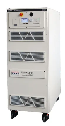
AZX Series – AC Power Source and Load with PHIL
The AZX Series optimized for PHIL applications. It has an interface via a low latency, perphase analog input. This feature amplifies control signals from real-time simulation systems for PHIL testing.
Expert Help You Can Trust
Don’t know where to start? That’s what our technical customer service
experts are here for.