The Fundamentals of Anti-Islanding Test Solutions

White Paper

Executive Summary
Unintentional islanding poses safety risks, including hazards to utility workers, equipment damage, and service disruptions. Anti-islanding protection is essential for distributed energy resources (DERs) like solar inverters, battery storage, and Vehicle-to-Grid (V2G) systems in which energy is pushed back onto the grid.
This white paper provides a comprehensive overview of anti-islanding concepts, testing applications, methods, and equipment considerations, and compliance standards.
Introduction to Anti-Islanding
What is Anti-Islanding?
As the demand for distributed energy resources (DERs) and electrification grows, ensuring safety and grid stability has become more critical than ever. One of the key safety mechanisms is anti-islanding protection —designed to prevent a solar inverter, for example, from continuing to feed power onto the grid when the grid has shut down.
Islanding occurs when a local energy generator continues to feed power into the grid during a grid outage, creating a hazardous “island” of energized equipment. Anti-islanding protection ensures that DERs or grid connected systems like EV chargers promptly disconnect from the grid during such events, safeguarding utility workers, customers, and equipment.
Testing for anti-islanding behavior is a mandatory requirement in compliance with standards like UL 1741 SA and IEEE 1547.1. Pacific Power Source’s AZX and GSZ Series grid simulators simplify this complex testing by providing a controlled, repeatable, and automated test environment that meets industry requirements.
Why Anti-Islanding Matters
Regulatory standards require grid connected devices to detect and shut down during grid loss scenarios within a specified time. Traditional anti-islanding tests involve precise control of voltage, frequency, and phase imbalance.
Key objectives of anti-islanding:
- Protect utility personnel from unexpected live circuits.
- Prevent damage to grid connected equipment due to voltage/frequency mismatch.
- Comply with interconnection standards (IEEE 1547, IEC 62116, UL 1741 SA) and relevant regional interconnection codes.
Key Applications
Anti-islanding testing is mandatory for DERs that export power to the grid such as:
- Solar PV Inverters
- Bidirectional EV Chargers
- Battery Energy Storage Systems (BESS)
- Vehicle-to-Grid (V2G) / Vehicle-to
- Everything (V2X) Systems
- Microgrids with Grid-Tied Modes
- Smart Inverters / Advanced Grid Support Inverters
Types of Anti-Island Tests
a. Passive and Active Detection Tests
Validate that DER can detect grid absence through voltage, frequency, or phase changes (passive) and/or intentional disturbances (active).
b. Load Imbalance (Non-Detection Zone – NDZ) Tests
Simulate worst-case condition where load closely matches DER output. Disconnect the grid and measure inverter trip time. NDZ testing verifies detection robustness.
c. Abnormal Voltage/Frequency Trip Tests
Ensure DER disconnects under out-of-spec grid conditions (under/ over voltage and under/ over frequency).
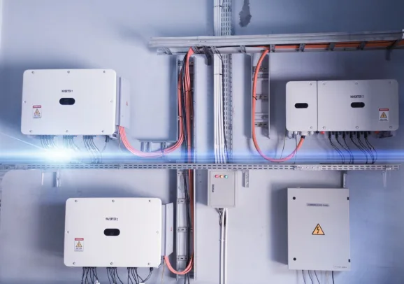
Typical Anti-Islanding Test Set-Ups
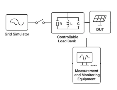
A typical anti-islanding test setup is designed to evaluate whether a grid-tied inverter or — distributed energy resource (DER) can reliably detect and respond to a loss of grid connection an event known as unintentional islanding .
A Typical Anti-Islanding Set-up
- Grid simulator
- A device under test (DUT)
- Controllable RLC load bank
- Measurement equipment
Together, these components replicate real-world scenarios in which the inverter must cease to energize an isolated section of the grid. This controlled environment allows for precise assessment of the inverter’s anti-islanding protection capabilities, as required by standards such as IEEE 1547, UL 1741, and IEC 62116.
Power Source (Grid Simulator)
- Programmable voltage, frequency, and impedance control
- Power rating 110–150% of DER output
- Low output impedance (mimic stiff grid)
- Fast transient response for clean disconnection
- Standards-compliant voltage/frequency excursions
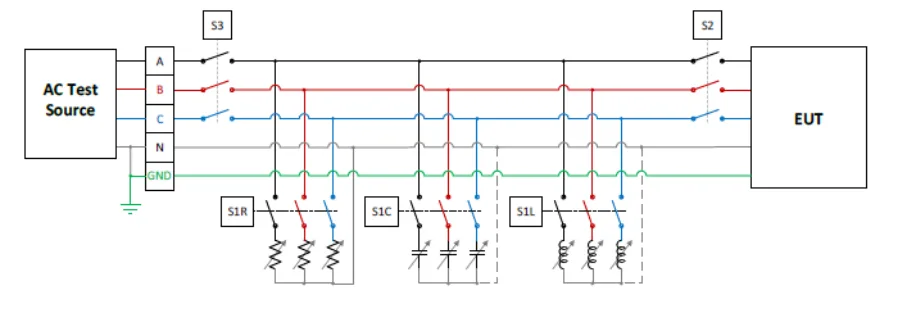
Load Bank
- Fine-tunable resistive, inductive, and capacitive elements. The adjustable load components may be formed by switching in and out of the circuit discrete component values or use of variable devices, i.e. electronic load.
- Match inverter output ±5% (NDZ)
- Power rating 110–125% of DER output
- Thermal stability, safety protections (overcurrent, isolation)
System Considerations
- Fast breaker (sub-cycle disconnection)
- High-precision power analyzer
- Minimized wiring impedance
- Synchronized measurement system
- Harmonic handling capability
Example Test Procedure Steps
Objective: Simulate an unintentional islanding event to ensure the inverter detects it and disconnects within the required trip time.
Below is an example of a test procedure based on IEC 62116 & UL 1741 SA:
| Step | Description |
|---|---|
| 1. Connect the System | Connect the DUT to a grid simulator, RLC load, and measurement equipment. This forms the test circuit. |
| 2. Configure the Load | Adjust the R, L, and C elements to closely match the inverter’s outputpower—this simulates the worst-case scenario for islanding detection. |
| 3. Establish Steady-State | Run the system under normal grid conditions. Verify stable voltage, frequency, and phase before proceeding. |
| 4. Simulate Grid Disconnection | Open the switch between the DUT/load and the grid simulator to create anislanded condition. The inverter now powers the load independently. |
| 5. Monitor and Record | Measure the time from disconnection to inverter shutdown. Record voltageand frequency behavior throughout the test. |
| 6. Apply Pass/Fail Criteria | The inverter must cease energizing within the allowed time (typically ≤ 2seconds per IEEE 1547). Failure to do so indicates non-compliance. |
RLC Load Capability
One of the required anti-islanding tests is to verify that DER ceases to energize and trip from the area EPS as specified in IEEE Std 1547 when an unintentional island condition is present. This requires an adjustable RLC load as part of the required test setup.
The AZX/GSZ/ELZ regenerative test solutions support islanding condition emulation when set to RLC Electronic Load mode by performing a real-time simulation of an RLC circuit.
It also accurately measures the disconnection time based on a programmable current threshold after it removes the simulated grid voltage to the DER test setup. This simplifies the required setup and time needed to perform IEEE 1547 PV Inverter and other distributed energy resources (DER’s) Anti-Islanding testing.
How does it work?
The RLC circuit is fully programmable, enabling multiple test conditions based on parameters such as Q factor, active power, reactive power, or current. By default, the system uses a Q factor of 1.0, but other Q factors can be set as needed. When the test is initiated, the RLC values are automatically computed using RMS measurements and the configured nominal frequency.
An integrated advanced scope function allows triggering based on islanding initiation and detection, eliminating the need for an external oscilloscope. A programmable trigger output is also available for synchronizing with external test equipment.
Testing is supported in single-phase, split-phase, or three-phase configurations. In three-phase mode, the system emulates an independent RLC circuit per phase, with individual programmability and measurement of disconnection time.
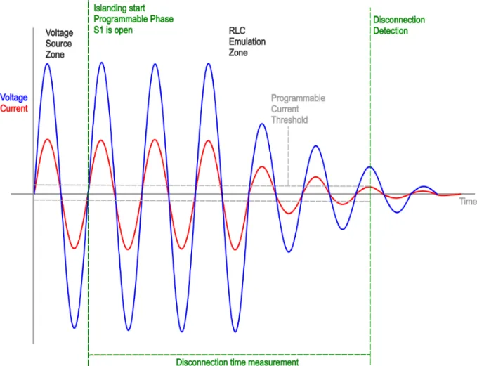
The islanding start phase is configurable via the “Update Phase” setting, which defaults to the voltage zero crossing. Figure 3 illustrates the operation for a single-phase setup.
Running the Test
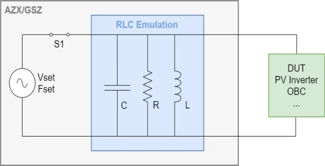
To begin the test, ensure the AZX/GSZ is enabled with nominal settings, and the DUT is stabilized at the desired power or current level.
When the islanding test begins, the internal switch (S1) is virtually opened, and the AZX/GSZ grid simulator emulates an RLC load in real time. The DUT continues supplying current, which the system uses to generate the corresponding voltage—accurately replicating a physical RLC circuit.
Current is continuously monitored, and disconnection time is recorded when the absolute current falls below a programmable threshold, with 10 µs precision. A programmable voltage safety margin (default: 125% of nominal) limits the emulated voltage; if exceeded, the system exits RLC mode and reverts to voltage source mode.
If the DUT disconnects as expected voltage decays naturally to zero. The system remains in RLC mode until the user manually ends the islanding operation or cycles the output to resume normal operation. Figure 4 shows a simplified diagram illustrating a typical islanding test sequence voltage and current waveforms.
Note: This feature is available in firmware version 5.4.0 and later. Currently, it can only be accessed via SCPI commands. A graphical user interface (GUI) implementation is planned for a future release.
PV Inverter Anti-Islanding Test Use Case
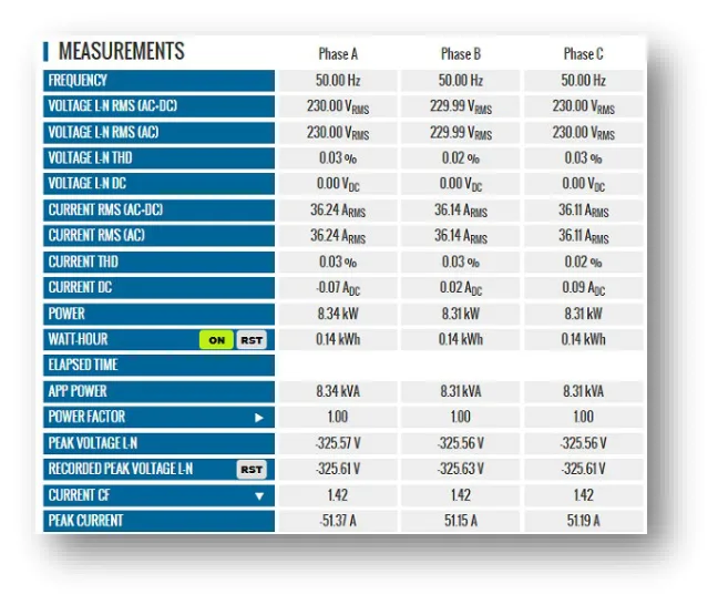
In the use case below, we are testing a PV Inverter at 50Hz. The objective is to verify compliance to regulatory antiislanding requirements.
In most cases, the RLC emulation results in the voltage collapsing toward zero after the disconnection of the DUT. However, depending on the configured RLC parameters and the DUT behavior, the voltage may rise instead, or the frequency may start to wander.
To protect the DUT from potential overvoltage conditions, it is recommended to configure both the islanding voltage margin and peak voltage protection settings on the grid simulator, appropriately.
By default, the islanding voltage margin is set to 1.25, allowing the output voltage to rise to 125% of the nominal value. If this threshold is exceeded, the RLC emulation is automatically stopped, and the source reverts to voltage source mode at nominal settings.
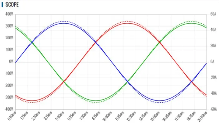
This scope capture shows the simulated three phase voltages and 50Hz frequency before removing the grid voltage:
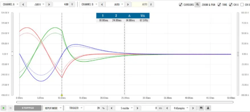
In this scope capture, the DUT successfully disconnected below, and as a result, the voltage collapsed, indicating a correct islanding response:
How to Select a Solution for Anti-Islanding
Pacific Power Source’s AGX and GSZ Series offer powerful grid emulation capabilities that allow users to replicate abnormal grid conditions with precision and repeatability. These systems are designed to simulate the challenging edge cases that grid-connected products must respond to.
| 10 Top Criterion | Why It Matters | Recommended Specs |
|---|---|---|
| Standards Compliance | Ensures testing validityand regulatory alignment | Meet mandatory standards with built-in functions tailoredfor DER testing, such as IEEE 1547, UL 1741 SA, IEC62116, etc. |
| Voltage/Frequency Range | Simulates global gridsand abnormal gridconditions | At least 120–480 V, 50/60 Hz, programmable slew rate |
| Power Capacity | Must match or exceed DUT output; sink power ifregenerative | Match peak DUT power; Regenerative capability |
| Impedance Control | Required to emulate realgrid disconnectscenarios | Adjustable impedance and RLC load emulation |
| Dynamic Response | Needed for simulatingfast transient or islandingevents | Fast slew rate, real-time waveform control. If the same ACsource is used to simulate the grid and then switch toelectronic load RLC mode after removing grid voltage, fastsync and impedance is important. |
| Phase Programming | Important for unbalancedor three-phase testing | Independent 1φ / 3φ control |
| Powerful DSPController | Programmable Grid Conditions with Fast Response Time | Easily simulate under/over voltage, frequency shifts, andphase imbalances with full control. |
| Programmability, Real-Time Scripting | Enables automation andcomplex scenariogeneration | API support, custom waveform playback; Createautomated anti-islanding test sequences using user-friendly tools or SCPI commands. |
| Third-Party Integration | Interoperability ensurescomprehensive testing | Easy integration with third party tools and software such as Yokogawa, Quality Logic, etc. |
| Flexible Multi-Channel Configuration | Allows for multi-channeltesting | Multi-modes are useful for single phase DER tests andeliminate additional test equipment. For example, onechannel could be set to Grid Sim, and a second channelcan be set to electronic load RLC mode. |
Pacific Power Source Test Solutions
Pacific Power Source’s AZX and GSZ Series grid simulators deliver a smart, application-focused approach to anti-islanding testing.
With built-in automation, grid emulation, and compliance support, we empower test engineers to move faster, test deeper, and ensure that grid-connected systems meet the strict safety and reliability standards of today’s evolving energy landscape.
If you’re looking for an Anti-Islanding Test Solution, consider the following products: AZX Series All-in-1 Power Source, GSZ Series Grid-Simulator or ELZ Series Regenerative Load.
Key Advantages include:
- Single, Split, Three-Phase
- Modular, Scalable Power: 30kW, 45kW, 55kW power levels
oParallel up to 550kWThree-Phase Systems Available up to 1.155MW - 4 Quadrant, Regenerative Power > 90%
- Wide operating Envelope0-240 Vac L-N / 0-415 Vac L-L and0-480 Vac-LN / 0-830 Vac-LL0-340 Vdc and 0-680 Vdc
- Extra Current
- Ultimate Flexibility with Mixed Channel Configuration
- Load Option: Several Emulation Modes plus Circuit Emulation RLC Mode
- SmartSource Suite Browser for enhanced control and visualization on any web browser

Expert Help You Can Trust
Don’t know where to start? That’s what our technical customer service
experts are here for.